Device setup
Mechanical design
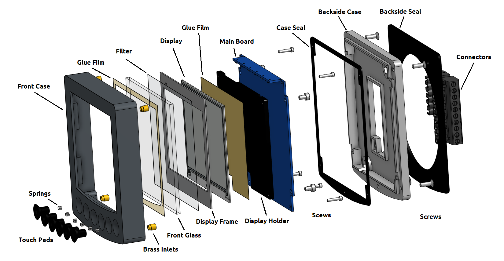
Fig.: Exploded view
The diagram above shows the structure of the OBP60. The device consists of individual components, which are described below.
- Touch Pads
The buttons are made of black anodized stainless steel (V2A) countersunk Allen screws. The buttons are screwed into the front shell of the housing using a sealant to achieve water resistance.
- Springs
The springs behind the keys serve to electrically contact the keys with the sensor surfaces on the circuit board.
- Front Case
The front panel of the housing accommodates the keys and contains the bonded front glass. The outer surfaces of the front panel are made of 2 mm thick plastic. The housing is hollow in some areas and contains a support structure with a 30% fill level. The housing is designed as a box structure, making it torsionally rigid.
- Brass Inlets
The brass threaded inserts reinforce the threads for the housing screws, as the plastic lacks sufficient strength to exert the necessary pressure to compress the housing gasket. The brass threaded inserts are thermally fused into the plastic and are secured against unintentional rotation within the plastic.
- Glue Film
The adhesive film is applied to the front panel and serves to waterproof the front panel to the inside of the housing.
- Front Glass
The 3 mm thick plexiglass front panel protects the display from environmental influences and mechanical damage from hard impacts. The front panel also acts as a highly effective UV filter. Its surface is anti-reflective, preventing direct reflections of sunlight. A special feature of the front panel is its ability to illuminate the e-paper display at night. Six RGB LEDs coupled light into the plexiglass at the top edge of the panel achieve this. The light from the LEDs is then diffused by diffusers within the plexiglass onto the e-paper display, resulting in even illumination across the entire display surface.
- Filter
An IR filter film is additionally applied to the back of the front glass to reduce the infrared radiation from sunlight and keep it away from the e-paper display. The infrared radiation is absorbed by the filter film and emitted to the front glass, because at maximum sunlight, up to 10 W of heat radiation hits the display.
- Display Frame
The display frame acts as a kind of mask, concealing unwanted areas of the display. Additionally, a small bridge is incorporated to shield the backlight from the display, preventing any ambient light from coupling into the glass of the e-paper display.
- Display
The display is an e-paper display capable of showing black and white and four shades of gray. The display resolution is 400 x 300 pixels. The pixel density, based on the display area, is 120 dpi. E-paper displays only consume power when updating the image. Even when switched off, the image content remains visible. This makes this screen technology very energy efficient.
- Glue Film
The adhesive film behind the display is used to attach the display to the display holder.
- Display Holder
The display bracket supports the e-paper display and prevents it from twisting. The e-paper display is very delicate, as it consists of two glass substrates with a total thickness of only 0.7 mm. The display is attached to the motherboard via screws using the display bracket.
- Main Board
The motherboard contains all electronic components on a double-sided circuit board. The LED board for the backlighting is mounted on the top side of the motherboard.
- Case Seal
The housing seal creates a watertight connection between the front and back shells. The seal is designed as a 1 mm thick surface seal.
- Backside Case
The rear housing shell closes off the back of the housing. Like the front shell, it is designed as a torsionally rigid box construction.
- Backside Seal
The rear panel seal seals the housing against the mounting opening. The seal is made of 2 mm thick neoprene material. This allows it to bridge minor irregularities and slight curves.
- Connectors
Removable connectors are attached to the back of the device for easy installation. The device can be powered and connected to bus systems via these screw-type connectors.
Main Board
The motherboard contains all electrical and electronic components such as:
Dual Core CPU ESP32-S3
Power supply
Display control
Sensor buttons
GPS receiver
RTC real-time clock
Backup Battery
Buzzer
Flash-LED
Backlight
Isolated drivers for bus systems (NMEA2000; NMEA0183, I2C)
External power supply
ESD protection circuits
USB-C

Fig.: Mainboard top
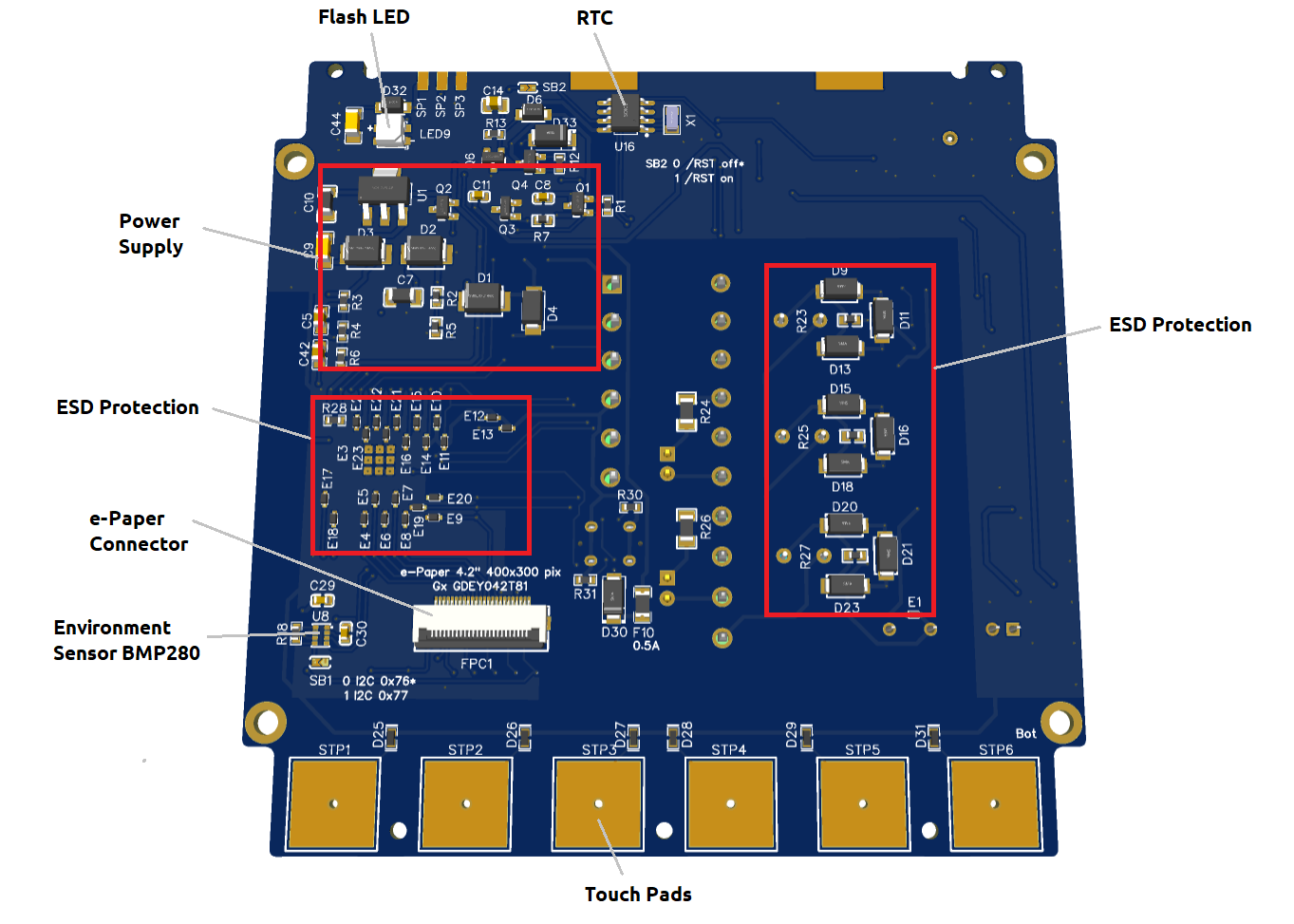
Fig.: Mainboard underside
Circuit boards
The circuit boards for the mainboard and the backlighting were designed as double-sided SMD boards with vias, masking lacquer and printing.
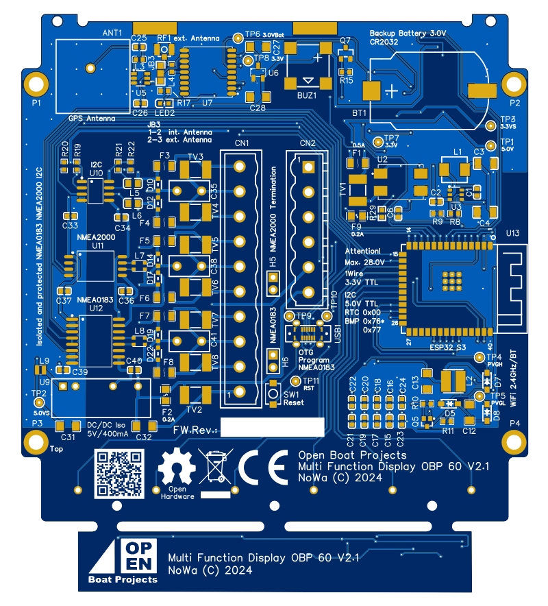
Fig.: Unpopulated circuit board top side
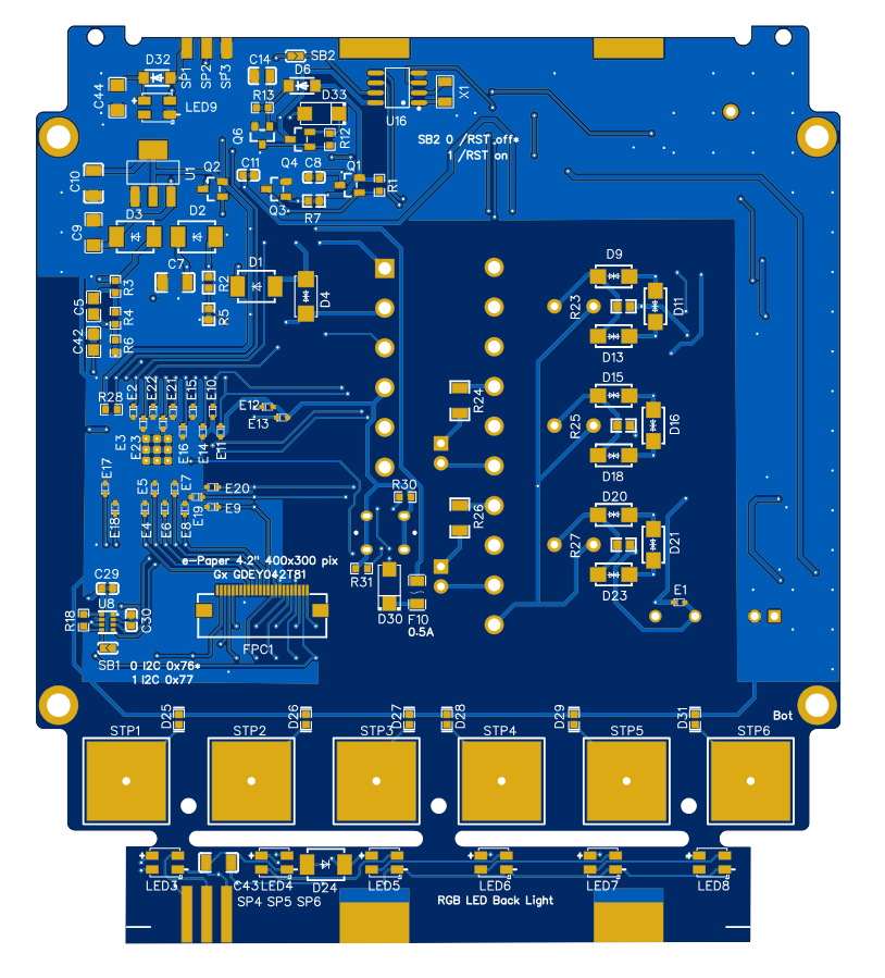
Fig.: Unpopulated circuit board underside
Circuit diagram and manufacturing data
The circuit diagram and circuit board were created using the online development tool EasyEDA. The documentation for manufacturing is listed below.

The manufacturing data, including the circuit diagram, Gerber data, parts list, and 3D data, are subject to Common Creative Lizenz (CC) BY BC SA 4.0. The OBP60 may be reproduced or modified, provided the authors are credited. There are no costs for private, non-commercial use. Commercial use is prohibited by the license. Derivative works are subject to the same license. If you intend to use the OBP60 commercially, please contact us via Kontaktformular. It is possible to acquire a non-exclusive right of use through a commercial license.