Commissioning
This section contains detailed information for the initial setup of your OBP60.
This is easiest if the device is not yet installed in the boat. To do this, connect the device to power via the rear power strip, and you can then make initial settings. This allows you to test the functionality before installing the device in the boat.
Hint
It is usually not enough to power the device only via USB-C, as not all functions of the OBP60 will then be available.
Protection concept
The OBP60 features a multi-stage protection concept. This is designed to prevent faults in the power supply network and on the data lines within the system from propagating. This ensures that the OBP60 does not fail completely despite faults and remains largely functional in critical areas. To achieve this, the bus systems are:
NMEA2000
NMEA0182
I2C
It is built isolated from the vehicle’s electrical system.
Warning
Please note that the 1-Wire bus is not protected against interference and must therefore be shielded. Only shielded cables should be used for the 1-Wire bus. GND must not be connected to any other external circuit components, as GND serves solely as the ground connection for the 1-Wire bus.
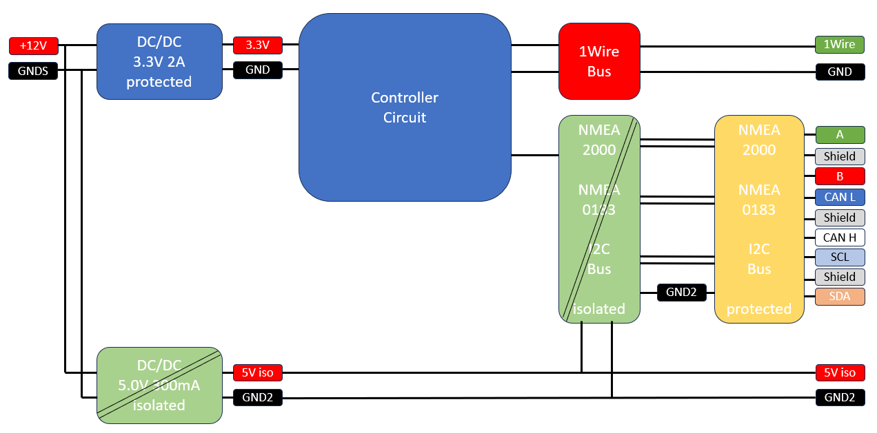
Fig.: Protection concept
The OBP60 includes an additional 5V power supply that powers the isolated circuit components. This additional power supply has outputs +5Viso and GND2, which are connected to connectors CN1 and CN2. These outputs can also power external circuits up to 200 mA.
Warning
Never connect the different ground potentials GNDS, GND, GND2 and Shield together! Doing so will negate the insulation and protective effect. The ground potentials must not be used interchangeably.
The different mass potentials have the following meaning:
GNDS- Ground of the supply voltageGND- Internal Mass of ElectronicsGND2- Ground of the isolated bus electronicsShield- Protective conductor for the cable shielding
The following image shows the protected and unprotected connections.

Fig.: Safe and unsafe areas
Power supply 12V/24V
The OBP60 is powered via connector CN2. Please use the connections +12V and GNDS.
The OBP60 switches on automatically when the power supply is connected. There is no separate on/off switch on the device. Use the +12V and GNDS terminals for power. Connect +12V to the positive terminal of the battery and GNDS to the negative terminal. These power supply terminals are:
Reverse polarity protected
Short-circuit proof
Surge-proof
ESD-protected
The permissible voltage range is 10V - 28V.
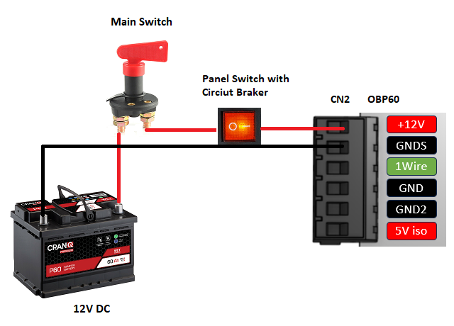
Fig.: Power supply
The OBP60 can be used in 12V and 24V on-board power supply systems. The internal fuse in the device will trip at voltages higher than 28V.
Warning
Use cable cross-sections of 0.5 to 0.75 mm² for the power supply wiring. The cables should be connected directly to the control panel and should not have any additional branches for other devices. Excess cable length should be avoided. If the power is tapped at other devices, or if the cable cross-sections are too small or the supply lines are too long, problems may occur when switching on the OBP60.
In some situations, it is more advantageous to supply power directly via the NMEA2000 bus. However, this requires a correct installation of the NMEA2000 bus. In this case, the power supply wiring to a control panel is unnecessary. Further details can be found in the chapter Bus systems.
Note
The device has a self-resetting fuse that automatically disconnects the power supply if the current draw is too high. You can reset the fuse by disconnecting the power supply to the OBP60 and eliminating the cause of the excessive current draw. Then wait a few minutes and reconnect the power supply.
Important
The internal fuse in the OBP60 only protects the device itself and not the power supply lines! Therefore, the OBP60’s power supply should be protected by an additional fuse of at least 5A on the boat’s electrical system. This is typically done via the fuse box, which controls the boat’s electrical circuits. This prevents fires caused, for example, by chafed or overheated power supply lines.
USB-C power supply
The OBP60 can also be powered via USB-C. However, the USB port must be able to supply sufficient voltage (5.1V) and current (up to 1A). The USB port on the OBP60 features reverse polarity protection, allowing simultaneous 12V/24V and 5V power inputs.
Note
Many USB computer ports don’t have a sufficiently high output current and share the available power with multiple ports. This can prevent the OBP60 from being powered directly from a PC. Cable quality and length are also crucial. Some cables have insufficient cross-sections, resulting in a high voltage drop along the conductors. The voltage at the USB-C output will then be too low. In such cases, use the additional 12V input on CN2 for power.
To test whether the USB-C power supply is providing sufficient voltage and current, a USB-C diagnostic tool can be used. The diagnostic tool is connected to the OBP60’s input, and the USB-C power cable is plugged into the diagnostic tool. The supplied voltage and current current consumption can be read on the display. The voltage should be at least 5.0 V. The current will vary depending on the current draw.
Hint
Depending on the USB-C diagnostic device used, only the power supply pins may be connected, and no data transfer may be possible. If you require communication via USB-C, you must disconnect the diagnostic device.
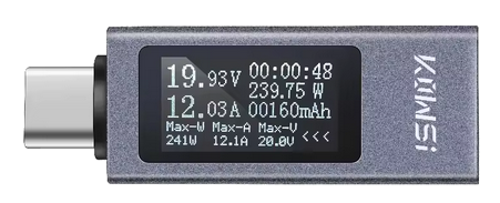
Fig.: USB-C diagnostic device
Installation
The OBP60 is installed from the back. The foam rubber gasket can be used as a template to mark the opening and holes in the cockpit wall. Remove the back cover before installing the OBP60. Insert the two hex screws into the designated recesses and secure them to prevent them from falling out. Before installation, check that the M5x25 screws are long enough. If necessary, replace them with screws of the appropriate length.
Warning
The heads of the hexagon screws should be glued into the recesses so that they are not pushed into the interior of the housing during installation and can cause a short circuit on the circuit board.
After that, the casing is completely reassembled.
Before installation, a 2 mm thick foam rubber gasket is placed between the back and the cockpit wall. This gasket can compensate for surface irregularities to a certain extent. The OBP60 is then secured using the washers and nuts.
Warning
Do not overtighten the nuts. The anti-rotation device or the back panel may be damaged.

Fig.: Device installation in cockpit wall
Hint
The GPS receiver’s antenna is located in the upper left corner on the back of the OBP60 (when viewed from the rear). There should be no large metal objects behind the growing area. Metal objects can interfere with or prevent GPS reception. If you experience reception problems, you can use an external GPS antenna.