Web-Flashtool
The Web Flash Tool allows you to transfer the firmware for the OBP60 to the device via a USB connection using a web browser. To do this, connect the OBP60 to a PC or laptop via the USB-C port and launch the Chrome or Edge web browser. The OBP60 has an integrated USB-to-serial converter for data transfer. Only the firmware can be transferred using the USB-C cable; operating the device via USB is not possible with this method.
Note
Web browsers other than Chrome or Edge are not currently supported, as the functionality for accessing a serial interface is not implemented in other web browsers.
Warning
Please note that the web flash tool can only be used with an OBP60 V2.1 that uses an ESP32-S3 N16R8 processor and a GDEY042T81 e-paper display. If you are using different hardware, you will need to compile a customized firmware version for your specific hardware. Follow the instructions in the Compile and download chapter.
- The following items are needed for the flashing process:
OBP60 (ESP32-S3 N16R8, E-Paper GDEY042T81)
USB-C to USB-A connection cable < 1.5m
Wire bridge 5 cm
PC with Chrome or Edge browser
- 1. Put the OBP60 into flash mode
Open the rear cover and connect
GND(CN2) toPin 27(ESP32-S3) using the jumper wire. Then connect the OBP60 to the PC using the USB cable. Once the USB interface is recognized, you will hear a sound on the PC. You can then disconnect the jumper wire betweenGNDandPin 27. The ESP32-S3 is now in flash mode.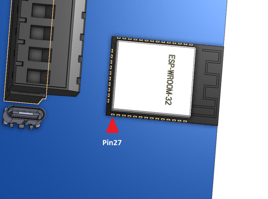
Abb.: Pin27 am OBP60
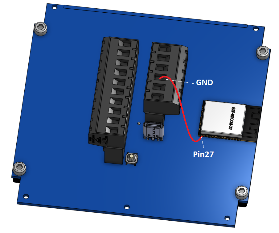
Fig.: Bridge between
GNDandPin 27
2. Start Flashtool
Next, visit the website of Online-Flashtools.
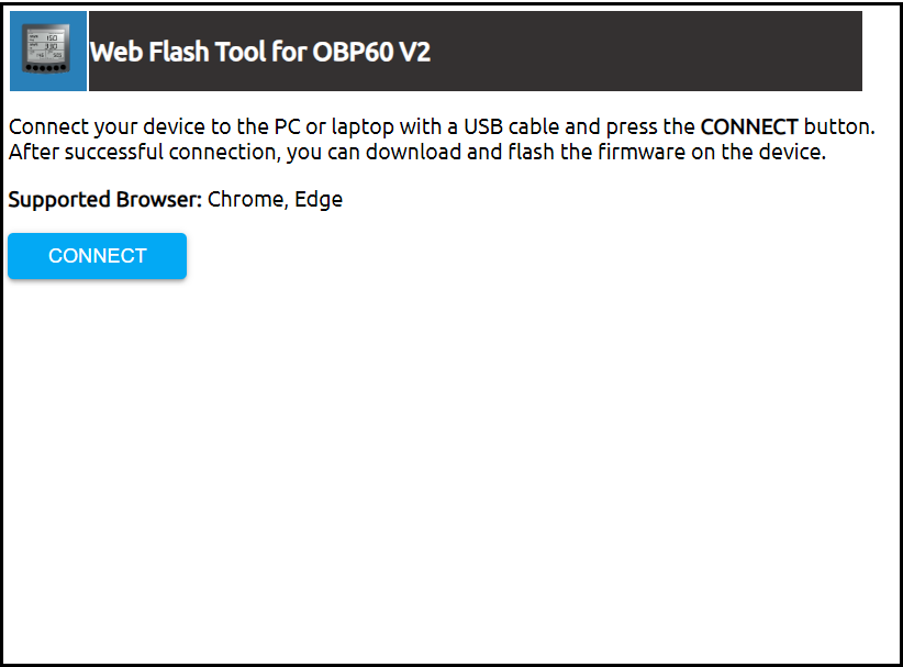
Image: Homepage Web-Flashtool
Then press Connect and select the appropriate serial interface. The interfaces may be labeled differently depending on your operating system.
Windows: USB JTAG/serial debug unit COMx
Linux: /dev/ttyACMx
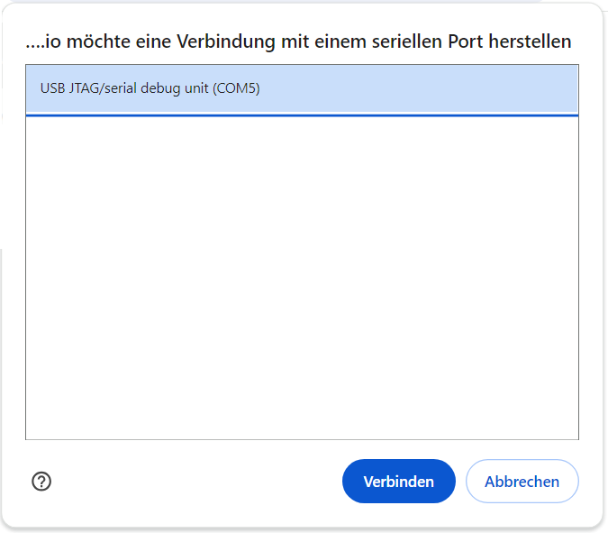
Fig.: Selection of the interface
Note
Note that other serial interfaces may also be in use in the system. Select the interface that appears in the system after connecting the OBP60 to the USB port. Do not use existing interfaces, as they are already in use.
- 3. Firmware transfer
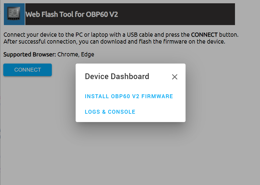
Fig.: Start flashing process
Start the installation process via
INSTALL OBP60 V2 FIRMWARE. A message will be displayed after successful transfer.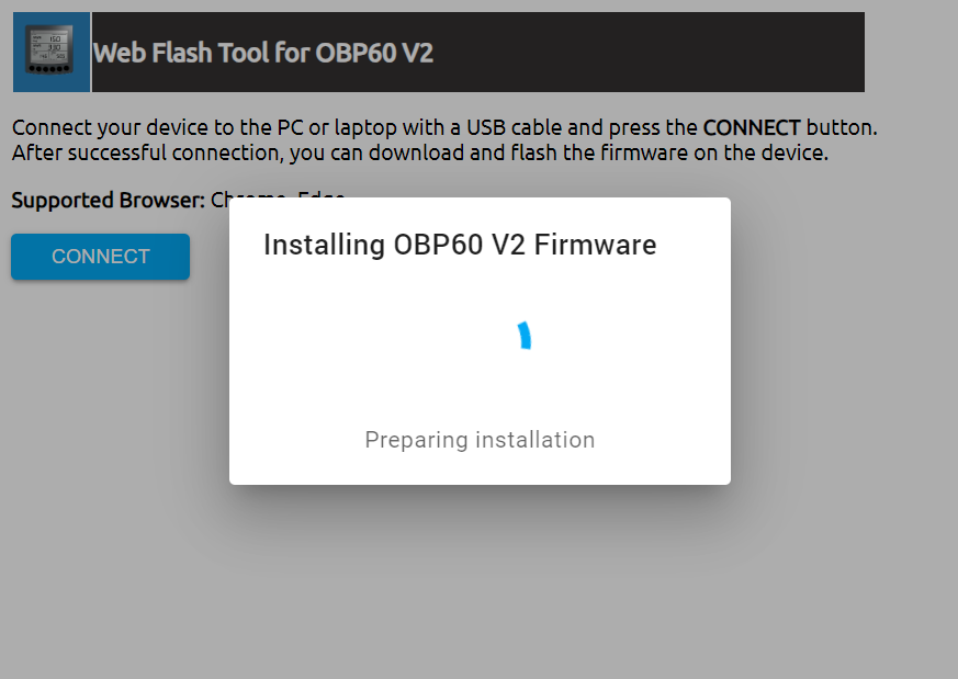
Fig.: Firmware transfer
- 4. Start OBP60
Disconnect the USB cable and connect the OBP60 to CN2 via
+12VandGND. A short beep will sound when the firmware starts. After a short time, a display page should appear. Depending on the settings, the OBP logo and the QR code for WiFi access may be displayed beforehand.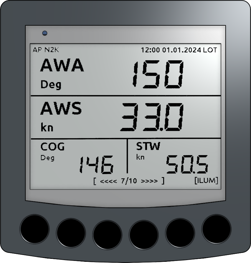
Fig.: Display page