Quick Start
This chapter deals with the initial setup of the OBP60, from unpacking to displaying the first data on the screen. The aim is to make the initial setup as easy as possible for users who are not yet familiar with the device.
Package contents
The package contains everything you need to assemble and connect the device, except for the connecting cable:
The device itself, the OBP60 Marine Display
A protective cap is important if you are mounting the device outdoors.
Seal for watertight mounting on a smooth surface
Fastening screws
Two terminal blocks to which the various cables are connected.
Two jumpers as coding plugs, with which the NMEA2000 and NMEA183 termination can be activated.
Initial commissioning
More detailed additional information can be found in the chapter Commissioning. Here is a brief overview of the first steps:
It is recommended to perform the initial setup of the device at your workbench. A 12V power supply is required. A USB-C cable, a computer, and NMEA simulation software are also useful.
This is what the device looks like from the back:
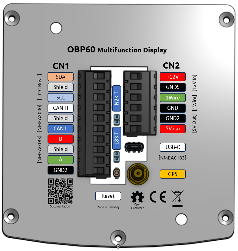
The 12V power supply is provided by the two uppermost pins on the right-hand CN2 connector, namely .12V and GNDS. USB-C is connected to the oval connector below the CN2 connector.
Hint
The device requires a 12V power supply to operate. Testing via a PC using only USB-C is not possible.
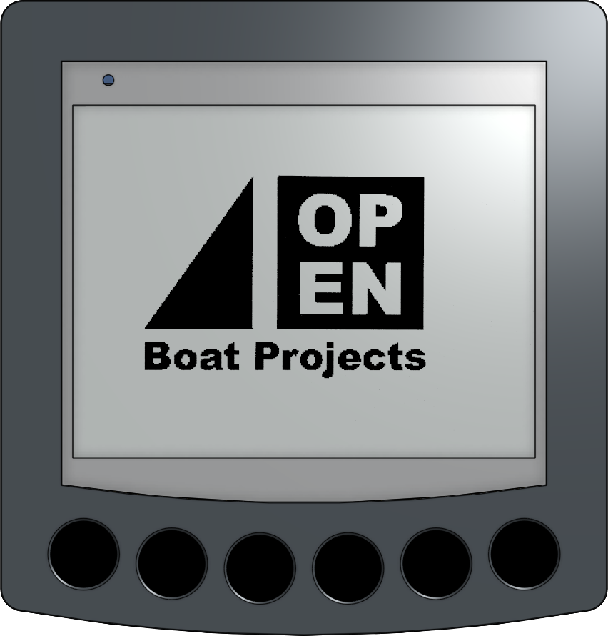
After switching on the power supply, the device beeps and displays this start screen:
Shortly afterwards, a QR code is displayed, which allows you to connect directly to the OBP60 via your mobile phone.
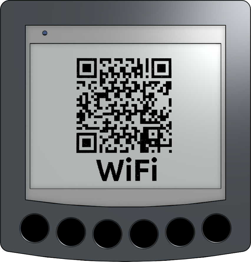
The device creates its own Wi-Fi network. In the network list, for example on Android, there is a QR symbol at the very bottom. Clicking on it allows you to scan the QR code, and the phone or tablet will then connect directly to the OBP60’s Wi-Fi network.
Note
If that doesn’t work, please select the Wi-Fi network with the ID “OBP60V2” and enter the default password “esp32nmea2k”. It’s advisable to change the password later.
Once the connection is established, the address of the OBP60 is entered. This is “OBP60V2.local”, alternatively, the IP address “192.168.15.1” can be entered directly.
Hint
If the connection fails, it may be because a VPN is active on the mobile device. The VPN must then be deactivated or reconfigured.
The status screen should then open directly:
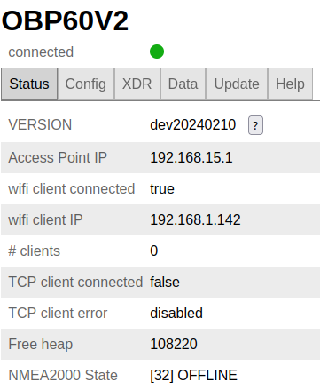
You can navigate to other pages using the tabs at the top of the screen:
Config: System settings and selection of the screens that the OBP60 should display.
XDR: Here, NMEA telegrams (XDR sentences) can be defined to transmit data for which there is no suitable NMEA 183 telegram.
DATA: Displays all data records defined for the device. If there is no actual data (e.g., because NMEA2000 is not yet connected), dashes are displayed here.
Update: Allows device firmware updates. First, download a new firmware file for the OBP60 to your mobile device. Then, go to this “Update” page, select the firmware file on your mobile device, and install it by clicking “Upload”.
Help: Displays a webpage with help information as soon as the OBP60 has internet access, e.g., as a client of an LTE router. This must first be configured.
Detailed additional information can be found in the chapter Configuration.
Hint
Above the tabs for the pages, a colored dot is visible. If it is green, the connection is intact; if it is red, it is broken.
Hint
A dropped connection is often due to the mobile device switching to a different Wi-Fi network. Therefore, automatic Wi-Fi reconnection should be enabled. If another Wi-Fi network is active, automatic reconnection to that network should be disabled.
Display pages
The OBP60 can display data it knows across up to 10 screens. You switch between screens by either swiping across the six buttons at the bottom or clicking one of the two middle buttons. In either case, you advance to the next screen.
Note
The OBP60 has an ePaper display. These displays offer particularly clear images and low power consumption. However, they also have the characteristic that a “refresh” is required regularly. Therefore, the display flickers at regular intervals or after page changes – this is normal.
Each page can be freely assigned one of the many layouts. Currently, for example, there are:
Pages with one, two, three or four numerical values
Wind rose with four additional data points
Compass rose with ship depiction
Clock
Wind pattern graph
Depending on the page, different data can be displayed. Which data is shown is configured in the web interface.
Here’s an example:
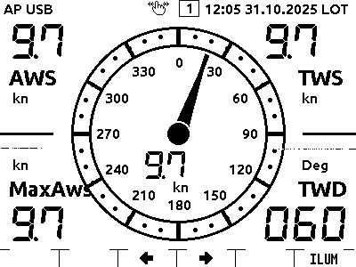
The top line displays the device status. Here you can see that the device is in Access Point mode (AP), receiving data via USB (USB), and that swipe gestures can be used (hand icon). The current page number is displayed in the middle, and the time and its specific time – in this case, Local Time (LOT) – are shown on the right.
The information displayed in the middle of the screen is relevant to the current screen.
The bottom line shows how the buttons are assigned. The screen backlight can always be turned on on the right, and the two middle buttons are for navigation. Swipe gestures are also possible.
More detailed additional information about the pages that can be displayed can be found in the chapter Config.
Operation
The OBP60 has six control buttons below the screen – more precisely, not physical buttons, but touch-sensitive buttons. Operation is via swipe gestures, or alternatively by pressing individual buttons.
For a swipe gesture, move one finger from right to left or vice versa across several buttons.
Pressing the buttons works as usual – simply place your finger briefly on one of the buttons. This is possible for the buttons that display a symbol at the top of the screen. The button functions change depending on the page being displayed.
More detailed additional information can be found in the chapter Controls.
Simulation
To familiarize yourself with the OBP60, it’s advisable to first connect it to a computer running an NMEA simulation via USB. NMEASimulator is a suitable example. Install the simulator, then select the USB port for NMEA183 within the simulator and connect the computer to the OBP60 via USB. Then start the simulation by clicking “Run”. Desired values can be entered on the simulator’s main screen.
Once the connection to the simulation is established, “USB” will be displayed in the upper left corner of the OBP60’s display. The transferred data will then appear on the display:
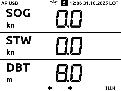
At the same time, they can be seen in the web interface of a logged-in mobile device.
Electrical connections
Detailed information on the electrical connections can be found in the chapter Power supply 12V/24V
For normal operation, at least a 12V power supply and a network, i.e. NMEA2000 or NMEA0183, must be connected.
The OBP60 does not have connectors for NMEA2000 or Seatalk NG, but rather terminal blocks to which the wires are directly connected. To establish a connection, an existing cable may need to be cut. The individual wires are then connected to the appropriate terminal block.
12V: Connect [+] and [-] to the two upper terminals on terminal block CN2
NMEA2000: The connections are CAN H, CAN L, and Shield. The color coding can vary depending on the system; in Raymarine Seatalk NG (which is also NMEA2000), CAN L is white and CAN H is blue. Shield refers to the cable’s insulation.
NMEA0183: This is where the signal lines for A and B as well as the shield are connected.
Montage
To mount the device, it should be securely screwed to a suitable surface. The two included hex screws are inserted from the inside, and then the housing is screwed back together.
The necessary cutouts for the cables and the two screws must be made according to the dimensioned drawing.
Then place the seal on the back of the housing, insert the screws and tighten them.
Further information on the installation of the OBP60 can be found in the chapter Installation